


The remarkable thing about helicopters is how effortlessly they seem to rewrite the rules of flight. A runway is optional, open space is negotiable, and the sky feels strangely closer when a machine can rise straight upward from a patch of asphalt, a ship’s narrow deck, or a rugged hillside where no airplane could dream of landing. That simple ability—lifting off vertically and hovering as if suspended by invisible threads—was once the kind of fantasy that belonged to legends. Igor Sikorsky (1889–1972), who played a defining role in bringing the modern helicopter to life, often compared these machines to the ancient stories of flying horses and magical carpets. In many ways, he wasn’t exaggerating.
Today, helicopters are the quiet workhorses of situations where precision matters more than speed. Picture a rescue crew hovering above a stormy coastline, lowering a cable toward stranded sailors. Imagine firefighters being flown straight over a burning forest to drop water exactly where it’s needed most. Consider engineers being lifted onto remote wind turbines, or a critically injured patient being rushed from a mountain trail to an emergency room in minutes rather than hours. Fixed-wing aircraft can travel astonishing distances at high speed, but they can’t maneuver through cramped spaces or pause above a single point without forward motion. When the mission demands agility, accuracy, or access to places where runways don’t exist, helicopters step in.
What makes this even more impressive is how long it took humans to figure out. The dream of vertical flight isn’t new at all; early records show people experimenting with spinning-rotor toys more than two millennia ago. Yet despite the fascination, the first truly practical helicopter didn’t appear until 1939, when Sikorsky’s persistent engineering finally cracked the problem. The delay wasn’t due to lack of imagination. It was because helicopters are astonishingly intricate machines. Every part—from the blades and hinges to the swash plate and tail system—has to cooperate with perfect timing. The aerodynamics are unforgiving, the mechanical demands extreme, and the controls require delicate coordination.
And still, the result seems almost effortless. A helicopter can climb vertically, hover motionless, drift sideways, pivot on the spot, or back away slowly as if it were moving along invisible rails. It raises a simple question that hides an incredibly complex answer: what exactly is happening that allows such a machine to stay in the air at all? To understand that, we need to step inside the world of lift, torque, rotor aerodynamics, and the interconnected systems that give helicopters their extraordinary abilities.
How does a helicopter actually stay in the air?
At its core, a helicopter obeys the same physics that keeps an airplane aloft. Both machines rely on lift: an upward force that pushes against gravity and counters the weight of the aircraft. If the lift is stronger than the weight, the machine climbs. If lift is weaker, it sinks. If the two are in balance, the aircraft can cruise or hover.
Airplanes generate lift with their wings, which are shaped as airfoils: cross-sections that are curved on top and usually flatter underneath. As the plane is pulled forward by its engines, air flows over and under each wing. Because of the wing’s shape and angle, the airflow ends up being turned downward behind the wing. Newton’s laws tell us that if the wing pushes the air downward, the air pushes the wing upward with an equal and opposite reaction. That reaction force is the lift that holds the airplane in the sky.
To get enough lift, a conventional airplane has to push a huge volume of air over its wings every second. That, in turn, forces certain design decisions. Wings have to be wide enough and long enough to generate sufficient lift. The aircraft must move quickly through the air, which means it needs powerful engines and streamlined shapes, and it must have a long runway to build up speed during takeoff and to slow down safely when landing. An airplane is, in a sense, committed to forward motion.
A helicopter solves the same lift problem in a very different way. It still uses airfoils, but it doesn’t rely on a long, fixed wing cutting through the air. Instead, it mounts long, narrow blades—also shaped like thin wings—on a central hub. These blades spin rapidly, driven by the engine through a transmission. Because the blades move through the air so quickly, they don’t need the body of the helicopter itself to move forward at high speed. The rotor creates its own airflow.
As the rotor spins, each blade “runs on the spot,” sweeping out a circular disc above the helicopter. Air is pulled down through this disc and forced downward in a powerful wash, often called the rotor downwash or downdraft. The blades, acting as rotating airfoils, force the air down; the air responds with an upward push, which becomes the lift that holds the helicopter up. In a typical medium-sized helicopter, the main rotor might spin at a few hundred revolutions per minute, fast enough that the blade tips are moving at extremely high speeds through the air even when the helicopter itself is stationary.
This approach gives helicopters capabilities that airplanes simply don’t have. Because they don’t depend on forward speed to generate lift, helicopters can rise vertically from a standstill, hover in one place, spin around almost on the spot, or move sideways and backward as easily as forward. The trade-off is efficiency: planes are generally faster and more fuel-efficient over long distances, but helicopters win when it comes to flexibility and precise low-speed maneuvering.
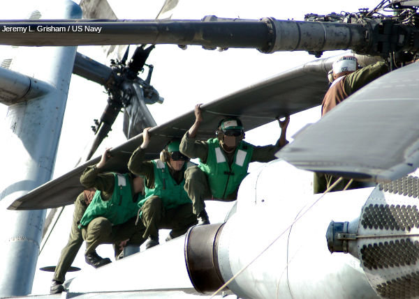
Photo: A group of US Marines supports the enormous tail rotor of a Navy helicopter during maintenance. The size and weight of the rotor tell you how crucial and heavily stressed these components are. Look closely at the curved leading edge of the blade: that airfoil shape is what makes lift as the rotor spins.
Helicopters, then, generate lift by pushing air down with spinning airfoils instead of fixed wings. But that only explains how they stay up. To really understand how they operate in three dimensions, we need to look at the main components that do all the work.
The main working parts of a helicopter
If you stripped the skin off a modern helicopter, you would discover a dense forest of mechanical parts: shafts, gearboxes, linkages, bearings, and structural members, all woven together around the crew, engine, and fuel systems. In practice, these machines contain thousands of individual components. Fortunately, to grasp how a helicopter functions, we only need to focus on a few major assemblies.
The central structure of the helicopter is called the fuselage. This is the main body that holds the cockpit, passenger or cargo area, fuel tanks, and many of the mechanical systems. Modern fuselages are typically made of strong but comparatively lightweight composite materials, aluminum alloys, and sometimes titanium in high-stress locations. The design has to survive vibration, aerodynamic loads, and sometimes even hard landings without being excessively heavy.
Inside or attached to the fuselage you will usually find one or two engines, a transmission, and one or more gearboxes. These parts work together to take the high-speed power from the engine and convert it into the precise rotational speed needed to drive the main rotor and the tail rotor. The transmission also has to route power and handle changes in torque as the pilot changes the load on the rotor system.
Most helicopters have one large main rotor mounted on top of the fuselage on a vertical mast, and a smaller tail rotor mounted on a boom at the back. Some designs use two main rotors instead of one, arranged in different ways (for example, at the front and rear, or coaxially on the same mast), but the idea is similar: one or more rotors provide lift and, with clever control, steering.
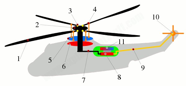
Artwork: A simplified cutaway view captures the essential mechanical parts of a typical helicopter. Each rotor blade is attached to the central rotor hub by a hinge that allows it to swivel, or “feather.” Short rods called pitch links connect each blade to a rotating upper swash plate. This plate sits on bearings above a lower swash plate that remains stationary. By sliding the swash plates up and down or tilting them slightly, the pilot can change the pitch of the blades either all together or at specific points in their rotation. A driveshaft connects the rotor mast to a transmission and gearbox, which in turn send power from one or two turboshaft jet engines to both the main rotor and the tail rotor. Though it looks bewilderingly complex at first, all of this machinery exists to do two jobs: spin the blades and change their angle to the air at exactly the right moment.
Helicopter engines and power systems

Early helicopters often used piston engines, also known as reciprocating engines, similar in principle to the engines found in cars and trucks. These engines rely on a series of pistons rapidly moving up and down in cylinders, turning a crankshaft and delivering rotational power. While piston engines can work for small, light helicopters, they have limitations. They tend to vibrate more, they are mechanically complicated, and their power-to-weight ratio is not as favorable as more modern alternatives.
Most contemporary helicopters, especially medium and large ones, now use gas turbine engines instead. These are closely related to the jet engines that power airliners, but they are adapted to drive a shaft rather than directly produce thrust. In a typical turboshaft engine, air is drawn into the front, compressed, mixed with fuel, and burned in a combustion chamber. The hot gas expands and spins a series of turbines. Some of these turbine stages drive the compressor, while others are coupled to an output shaft that delivers rotational power to the helicopter’s transmission.
Compared to piston engines, turboshafts are usually smoother in operation, as they have fewer rapidly reciprocating parts and spin continuously instead. They can provide a lot of power for relatively little weight, which is critical in aviation. They are also generally more reliable when maintained properly, which matters enormously for something that spends its time off the ground.
Helicopters can arrange these engines in different ways. Some are mounted horizontally just behind and beneath the main rotor, feeding power straight into the transmission above. Others are mounted on either side of the rotor mast, as you often see on military helicopters such as the Seahawk or Apache. The transmission then gathers power from both engines, balances their contributions, and passes the resulting torque into the rotor mast and tail rotor driveshaft.
In a conventional jet airplane, the engine’s hot exhaust is accelerated out the back, directly providing thrust. In a turboshaft-powered helicopter, the exhaust is less important than the mechanical power being extracted from the gas flow. The engine’s real job is to spin the rotor system through the transmission, giving the pilot fine control over how fast the blades turn and how much lift they generate.
The main rotor system
The most recognizable feature of any helicopter is its main rotor: the large spinning disc of blades above the fuselage. It is tempting to think of this rotor as a simple “fan” that blows air downward, but that sells the engineering short. To see why, we need to bring in a fundamental principle of physics: Newton’s third law of motion.
Newton’s third law states that for every action, there is an equal and opposite reaction. When a force causes something to move in one direction, an equal force pushes in the opposite direction on something else. In a helicopter, the engine and transmission apply a twisting force—torque—to the rotor mast. This torque makes the rotor blades spin in one direction. According to Newton, the helicopter’s fuselage feels an equal torque in the opposite direction and tends to rotate the other way.
If nothing countered that reaction, the body of the helicopter would start spinning under the rotor like a top, making controlled flight impossible. This is a crucial problem in helicopter design: how do you generate lift with a spinning rotor without causing the whole airframe to pirouette out of control? The answer is to provide counter-torque.
One way to do this is to use two main rotors instead of one, arranged so that they spin in opposite directions. When one rotor turns clockwise and the other turns counterclockwise, their torques cancel out, and the fuselage no longer has a tendency to rotate. Some designs mount both rotors on the same mast, stacked vertically and spinning in opposite directions. This is known as a coaxial rotor configuration. Others, like the large CH-47 Chinook, put one rotor at the front and another at the rear. This is the tandem rotor configuration, where each rotor sits on its own mast and they counter-rotate to keep the aircraft stable.
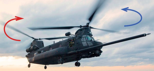
Photo: A CH-47 Chinook helicopter uses a pair of huge rotors, one at the front and one at the back, spinning in opposite directions. This cancels out torque and allows the helicopter to carry heavy loads without relying on a tail rotor. The design is ideal for military transport, where lifting power and stability are crucial.
Apart from their configuration, rotor blades themselves can be built in different ways. The way each blade is attached to the hub and allowed to move determines how the rotor behaves under varying loads.
A rigid rotor system attaches each blade to the hub with a hinge that allows it to twist (feather) but not to flap up and down or move forward and backward much. This hinge, often called a feathering or pitch hinge, lets the blade change its angle relative to the oncoming airflow. That ability to adjust pitch is essential for controlling lift.
Semi-rigid rotor systems still allow feathering, but also include a teetering or flapping hinge. This hinge lets the blades move slightly up and down as they rotate, helping to absorb loads and keep the rotor stable when the helicopter is maneuvering or flying through turbulent air.
Fully articulated rotor systems go a step further. In addition to feathering and flapping hinges, each blade usually has a drag or lead-lag hinge. This hinge lets the blade swing a little ahead of or behind its nominal position in the rotational circle. These extra degrees of freedom help the rotor cope with complex aerodynamic and inertial forces, distributing loads and preventing damage. The trade-off is added mechanical complexity and maintenance.
Engineers choose between rigid, semi-rigid, and fully articulated designs depending on the size, speed, role, and performance requirements of the helicopter. Each option comes with advantages in handling and disadvantages in cost, maintenance, and mechanical difficulty.
Tail rotor and anti-torque systems
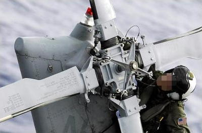
Photo: The tail rotor of a Seahawk helicopter is driven by a long shaft running through the tail boom from the main transmission. The blades can change their pitch as they spin, which allows the pilot to generate more or less sideways thrust and rotate the helicopter’s nose left or right while hovering.
On helicopters with a single main rotor, the torque problem is usually solved with a smaller rotor mounted at the tail. This tail rotor is essentially a sideways propeller driven by a long driveshaft connected to the main transmission. By pushing air sideways, it produces a force that counteracts the fuselage’s tendency to spin opposite the main rotor.
Sometimes designers protect the tail rotor by surrounding it with a ring or building it into a recess in the tail. In this configuration, called a fenestron or fan-tail, the rotor sits inside a shrouded opening. This can reduce noise, improve safety for people around the helicopter, and make the aircraft less vulnerable to damage from obstacles.
Another approach, known by the acronym NOTAR (short for “no tail rotor”), eliminates the exposed tail rotor entirely. Instead, the tail boom is used as a kind of duct. Air is forced through it and expelled through carefully placed slots and vents along one side of the tail. This stream of air interacts with the airflow around the boom, creating a sideways force that counters the torque from the main rotor. A jet of air from an opening near the end of the boom provides additional control. NOTAR systems can reduce noise and the risk of accidents involving the tail rotor, but they add their own mechanical and aerodynamic challenges.
Whatever method is used—tail rotor, fenestron, or NOTAR—the goal is the same: prevent the helicopter from spinning uncontrollably around its mast. Damage to the tail rotor or its drive system is therefore extremely serious. If the tail rotor fails in flight on a conventional single-rotor design, the pilot has to react immediately using emergency procedures to keep the helicopter controllable. Even then, the situation is dangerous and often leads to an accident.
Many helicopters also have a vertical tail fin or pylon at the rear. At higher forward speeds, the airflow over this fin helps counter some of the torque from the main rotor, reducing the demand on the tail rotor and improving efficiency.
How a helicopter hovers and steers
If the main rotor just spun like a fan, the helicopter could go up and down, but that would be about it. The real magic lies in how the rotor blades change their angle as they spin, and in how the pilot commands those changes. A helicopter must be able to rise, descend, stay at a fixed height, move forward, backward, and sideways, and rotate around its vertical axis. All of these motions depend on precise control of lift and thrust in different directions.
To manage this, the pilot works with five key controls: two hand-operated levers known as the collective and the cyclic, a throttle, and two foot pedals. These controls don’t act independently; most maneuvers require the pilot to coordinate several of them simultaneously. That coordination is one reason why helicopter flying demands such concentration, especially in demanding conditions.
Hovering in place
When the rotor blades begin to spin, they generate lift as air flows around their airfoil shapes. If there is not yet enough lift to overcome the helicopter’s weight, the aircraft remains on the ground. As the pilot increases engine power and changes the blades’ pitch, the lift grows. Eventually, the upward force equals the weight and the helicopter becomes light on its skids or wheels. A little more lift and it gently rises into the air.
If the lift is greater than the weight, the helicopter climbs. If the lift drops below the weight, it descends. Hovering happens in the narrow range where lift and weight are in careful balance. The pilot must constantly make tiny adjustments to account for wind, turbulence, and changes in load. Hovering is dynamic, not static; the helicopter is always making small corrections.
The main tool for controlling overall lift is the collective pitch control, usually just called the collective. This lever changes the pitch angle of all the main rotor blades by the same amount at the same time. Imagine each blade twisting slightly so that it bites into the air more steeply or more shallowly. A steeper angle usually means more lift, though it also increases drag, which the engine must overcome. A shallower angle produces less lift and less drag.
For liftoff, the pilot raises the collective, increasing the pitch on all blades so they cut the air more aggressively and generate a stronger downward wash. To descend, the pilot lowers the collective, reducing pitch and letting the helicopter sink under its own weight.
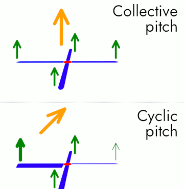
Artwork: A simple diagram can help visualize how the collective and cyclic pitch controls affect the rotor. In the upper illustration, the collective increases the pitch of all the blades equally, so the rotor generates more lift and the helicopter moves straight up. In the lower illustration, the cyclic changes the pitch of the blades selectively as they rotate. In this example, the blades create more lift on one side of the rotor disc than on the other, so the net lift is tilted, and the helicopter is pushed in a particular direction.
Inside the rotor system, the collective’s motions are transmitted through the swash plate assembly. The main rotor blades are attached to the hub by feathering hinges and connected to vertical rods called pitch links. These pitch links, in turn, attach to the upper swash plate: a metal disc that spins with the rotor but can slide up and down along the mast.
Underneath the rotating swash plate is a second disc, called the stationary or lower swash plate. This lower plate does not rotate with the mast. Instead, it sits still, connected to the pilot’s controls by linkages and pushrods. When the pilot pulls up on the collective, both swash plates move upward together, pushing the pitch links and increasing the pitch of all blades. Pushing the collective down reverses the motion, lowering the swash plates and reducing blade pitch.
At the end of the collective lever is usually a twist-grip throttle or, in many modern helicopters, a system that automatically adjusts engine power. In simple designs, the pilot rolls the throttle to increase or decrease engine speed, much like twisting the grip on a motorcycle. More engine power means the rotor can maintain its RPM and lift even when the blade pitch and aerodynamic load increase. In more advanced machines, an engine governor automatically boosts or reduces power to keep rotor speed within a narrow, safe range while the pilot concentrates on flying.
Directional steering in flight
The same rotor system that lifts the helicopter also steers it. To move in a particular horizontal direction, the helicopter needs more lift on one side of the rotor disc than on the opposite side. That difference tilts the total lift vector, and the helicopter moves in the direction of the tilt.
This is achieved with the cyclic control, often called the cyclic stick. This hand-operated control functions somewhat like a joystick. When the pilot moves the cyclic forward, backward, left, or right, the rotor blades are made to change pitch at specific points in their rotation. As each blade sweeps around, it experiences different aerodynamic loads. By carefully timing how its pitch changes, the helicopter can create more lift on one side of the disc and less on the other.
The swash plate system again plays a starring role. The upper swash plate, which spins with the rotor, is attached to each blade via the pitch links. The lower swash plate can tilt relative to the mast without spinning. When the pilot moves the cyclic, linkages tilt both plates in the desired direction. As they tilt, the upper plate carries the pitch links along, causing each blade to increase or decrease its angle at particular points in its rotation.
Suppose the pilot wants to fly to the right. Pushing the cyclic to the right tilts the swash plates in that direction. As the blades rotate, those on the left side of the helicopter encounter the swash plate at a position where their pitch is increased, generating more lift. Those on the right side experience a reduced pitch and produce less lift. The overall lift vector tilts to the right, and the helicopter begins to slide and then fly in that direction.
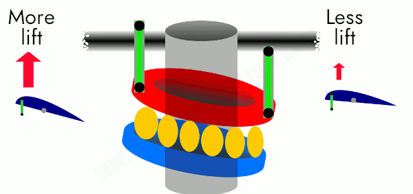
Artwork: The swash plate sits at the heart of the control system. A fixed lower plate surrounds the rotor mast and can tilt in any direction. A rotating upper plate sits on top of it, spinning with the mast. Four or more pitch links connect this upper plate to the rotor blades. When the lower plate is tilted using the cyclic, the upper plate tilts with it, forcing some blades to increase pitch and others to decrease pitch as they sweep around. The result is a rotor disc whose lift is stronger on one side than the other, steering the helicopter exactly where the pilot wants it to go.
In addition to moving forward, backward, and sideways, the helicopter must also be able to rotate about its vertical axis—what pilots call yaw. This is where the tail rotor and the antitorque pedals come in. The two pedals at the pilot’s feet control the pitch of the tail rotor blades. Pressing one pedal increases the tail rotor’s thrust, while pressing the other reduces it. Because the tail rotor pushes against the fuselage, changing its thrust makes the helicopter rotate clockwise or counterclockwise.
In a single-rotor helicopter, these pedals do double duty. At low speeds and in hover, they mainly control heading: which way the nose points. At higher speeds, they also help trim the aircraft so that it flies straight and doesn’t require constant sideways cyclic to track a straight line.
In tandem rotor helicopters like the Chinook, which don’t have a tail rotor, the pedals work differently. Instead of changing a tail rotor’s pitch, they alter the swash plate settings of the front and rear rotors in opposite ways. By increasing the pitch on one while decreasing it on the other, the helicopter can rotate while still maintaining overall lift.
How helicopter rotors really work
Everyone knows the obvious fact: helicopter rotors rotate. That is literally where the name comes from. But the fascinating part is not just that they spin; it is that the blades can also twist and move in subtle ways as they go around. This constant, carefully controlled motion is what makes hovering, climbing, and precise maneuvering possible.
If you want a rough physical analogy, stand up and stretch your arms out horizontally, like rotor blades. Start slowly turning your whole body around in place. While you’re turning, swing your arms slightly up and down and twist them at the shoulders so your palms point at different angles. Your body rotation is like the spinning mast; your arms are like rotor blades changing pitch and flapping as they circle. Now imagine you are doing all of that several times each second, with your arm muscles producing exactly the right amount of force at every moment, and you’ll have the tiniest taste of what a helicopter rotor system is doing mechanically.
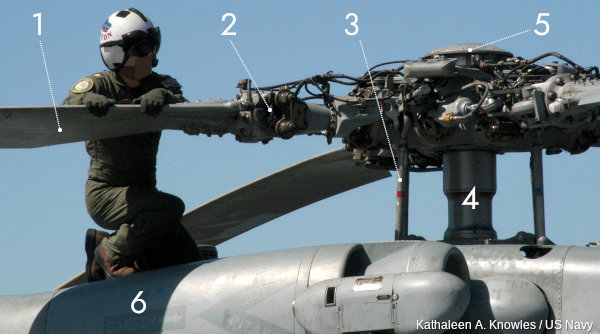
Photo: A Navy engineer inspects the rotor assembly of a Seahawk helicopter. The maze of rods, hinges, bearings, and fittings shows how much is going on above the pilot’s head. Each part plays a role in letting the blades twist and move just enough, but not too much.
Underneath the rotor hub, several key parts collaborate to make the blades respond correctly to pilot input and aerodynamic forces:
-
The rotor blades have an airfoil cross-section, similar to airplane wings but often narrower and longer. This shape is carefully designed so that as the blade moves through the air, it generates lift efficiently over a wide range of speeds and angles.
-
Each blade is mounted so that it can swivel around its feathering hinge. This hinge is the pivot point that allows the blade to change pitch—twisting slightly so its angle to the airflow increases or decreases. Pitch changes are how the helicopter controls lift on each blade.
-
The vertical pitch links transmit movement from the swash plate to the blades. When the swash plate moves up, down, or tilts, it pushes or pulls on the pitch links. These, in turn, twist the blades around their feathering hinges, adjusting pitch continuously as they rotate.
-
The rotor mast is the central shaft that carries power from the transmission up to the hub. When the engine turns the mast, the entire assembly—hub and blades—rotates. The mast must be extremely strong and precisely aligned, as it carries the full aerodynamic loads produced by the rotor.
-
A streamlined cap or fairing often sits above the hub. This component, sometimes called the rotor head cap, helps smooth out airflow, reducing aerodynamic drag and protecting sensitive parts beneath it.
-
Many larger helicopters use two turboshaft engines, one on each side of the rotor system. The transmission merges their power and feeds it up the mast and back to the tail rotor. If one engine fails, the remaining engine may still generate enough power for the pilot to control the descent and attempt a safe landing, which is crucial for safety over hostile terrain or open water.
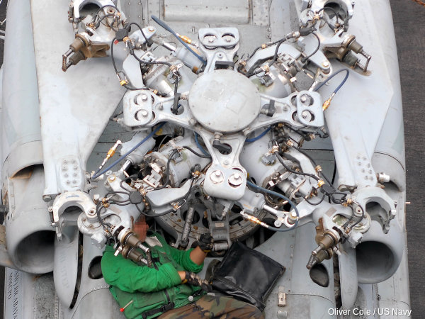
Photo: From directly above, the complexity of a Seahawk’s rotor mechanism becomes even more apparent. The folded blades, neatly aligned along the fuselage, allow the helicopter to occupy less deck space on an aircraft carrier. Meanwhile, the open engine bays and exposed hub reveal just how tightly packed and interdependent all the components are.
How Sikorsky created the modern rotor design
The elegance of the modern helicopter rotor did not appear overnight. It was the result of long, stubborn experimentation, much of it driven by Igor Sikorsky. Before he became famous for his helicopters, Sikorsky had already designed and flown fixed-wing aircraft, including some of the first large multi-engine airplanes. But he remained fascinated by the idea of vertical flight.
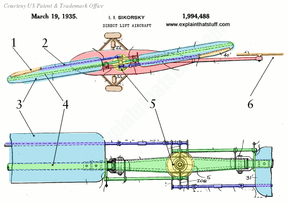
Artwork: A simplified version of Igor Sikorsky’s early rotor patent drawings shows ideas that still influence modern helicopters. Colored highlights emphasize key parts such as the adjustable ailerons on the blade tips, the control rods, and the central hub powered by an engine beneath.
In the early 1930s, Sikorsky filed a patent for what he called a “direct lift aircraft,” a flying machine capable of going straight up and down and hovering in place. The patent diagrams reveal a rotor system with many of the same elements used in helicopters today: adjustable blades, control rods, and a mechanism for changing their pitch as they rotate.
In his design:
-
Each rotor blade carries an aileron at its tip, a small hinged surface that can be tilted to alter the lift distribution along the blade. On Sikorsky’s drawing, these are highlighted at the outermost part of each blade.
-
A network of rods and linkages connects these aileron surfaces to the control system. By moving these rods, the pilot could change the angles of the ailerons as the rotor turns.
-
Sikorsky envisioned two main blades forming what he called a “lift propeller.” Together, they would generate enough lifting force to keep the aircraft airborne and controllable.
-
The blades were not rigidly fixed. They could swivel on supporting rods, allowing them to tilt as they spun. This movement was key to letting the rotor respond to changes in load and pilot commands.
-
At the center, the rotor turned around a hub mounted above the engine. The hub had to distribute power smoothly while also allowing the blades to move as needed without overstressing the structure.
-
Importantly, the same engine would power both the main rotor and a smaller tail rotor. This combination—one main rotor to provide lift and thrust, and a tail rotor to balance torque and provide yaw control—was a crucial breakthrough. Sikorsky noted that using a single main rotor instead of multiple lifting rotors made the aircraft lighter, structurally simpler, and cheaper to build. These benefits helped his design win out over earlier, more complicated concepts.
Strengths and weaknesses of helicopters
 airplane. The classic example is the Harrier. Instead of a rotor, it uses swivel nozzles to redirect jet exhaust downward for hovering, then rotates them backward for forward flight. It blends helicopter-like vertical ability with the speed of a jet, though at considerable technical cost.")
Helicopters offer a set of advantages that no other flying machine can quite match. The most obvious is their independence from runways. While a jet or turboprop needs a strip of reasonably smooth, clear land to take off and land, a helicopter only needs a small, relatively flat patch—maybe the roof of a hospital, the deck of a ship, a small clearing in a forest, or a patch of desert. That makes them invaluable in emergencies, remote areas, and crowded cities.
They also excel at precision work. A helicopter can hover above a specific point while lowering rescue personnel on a cable, delivering cargo with a winch, or keeping its sensors trained on a moving target. It can operate from ships at sea, move between skyscrapers, and set down in places where building a runway would be impractical or impossible.
On the downside, helicopters pay a price for this flexibility. Their moving rotor systems are mechanically complex and subject to high stresses. All the hinges, bearings, linkages, and driveshafts require careful inspection and regular maintenance. Compared to many airplanes, helicopters are more expensive to operate per hour of flight, and their cruising speeds are usually lower.
From a pilot’s point of view, helicopters and airplanes are almost different species. A helicopter pilot often has to use both hands and both feet actively at the same time, especially during hover and low-speed maneuvering. Small disturbances in wind or load can require quick, precise corrections. That doesn’t mean helicopters are “harder” in some absolute sense, but they demand a different set of skills and reflexes.
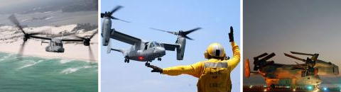
Photos: Another hybrid approach is the V-22 Osprey, a tilt-rotor aircraft. Its giant rotors can point upward like a helicopter’s, letting it take off vertically, then rotate forward to act like propellers on an airplane wing. This tries to capture the best of both worlds—helicopter-like flexibility and airplane-like speed—while inheriting some of the complexity of each.
A short history of helicopter development
“A flying machine offering reasonable speed and which would be controllable and safe, also combining take-off and landing ability in a small area, would be of great value and would be, unquestionably, in considerable demand.”
Igor Sikorsky wrote those words around 1930, long before helicopters became a routine sight in news footage and city skies. His prediction turned out to be correct, but it took centuries of trial-and-error experiments to reach the point where his vision could be realized.
Here is a brief tour through some of the milestones on the road to the modern helicopter:
-
Around 400 BCE – A Chinese text describes a small toy that behaves like a primitive helicopter. Feathers attached to the top of a stick spin when the stick is twisted between the hands and released, causing the device to dart upward through the air. It’s a simple demonstration of rotor-based lift.
-
1483 – The Italian artist and inventor Leonardo da Vinci sketches a “helical air screw,” a device with a spiral-shaped rotor that he imagined could lift into the sky if spun fast enough. The design never left the drawing board, but it shows that the idea of vertical flight was already firmly in human imagination.
-
1754 – Russian scientist Mikhail Lomonosov builds a model with two small rotors turning in opposite directions, driven by a mechanism of gears. This coaxial arrangement foreshadows later designs that use counter-rotating rotors to cancel torque.
-
1796 – British aviation pioneer Sir George Cayley experiments with spring-powered and elastic-powered helicopter models that can climb to significant heights. In 1843, he sketches a full-sized helicopter with two rotors. Unfortunately, the steam engines of his era are far too heavy and inefficient to power such a craft into practical flight.
-
1880s – The prolific American inventor Thomas Edison investigates helicopter designs, including ones driven by electric motors. He appreciates the potential advantages of electricity as a power source, though the technology is not yet mature enough for man-carrying vertical flight.
-
1901 – Igor Sikorsky, then a young Russian engineer, builds a small helicopter model powered by a rubber band. The modest toy is the seed of a lifelong effort that will eventually reshape aviation.
-
1904 – French researcher Charles Richet constructs a small helicopter that can lift itself, but not yet a pilot. It demonstrates that the basic idea works, though more power and better control are needed.
-
1907 – Louis Breguet, a student of Richet, and his brother build the Breguet-Richet gyroplane, a machine with four rotors arranged in a square. It can lift briefly to a height of about a meter, though control is minimal. That same year, Paul Cornu in France builds another early helicopter that manages brief hops of around twenty seconds with a person on board.
-
1916 – Austrian aerodynamicist Theodore von Kármán participates in designing the PKZ-1, an electrically-driven helicopter-like machine that can lift three men. Although it is not a practical helicopter in the modern sense, it shows just how many different paths inventors explored.
-
1920 – Spanish engineer Juan de la Cierva invents the autogyro, a hybrid aircraft with a free-spinning rotor above a conventional airplane fuselage. The rotor provides lift while an engine-driven propeller provides forward thrust. Autogyros can land and take off in shorter distances than airplanes and help bridge the gap to true helicopters.
-
1931 – After years of testing and refining his ideas, Igor Sikorsky patents a practical helicopter design. It features the now-familiar layout: a single main rotor for lift and a smaller tail rotor for counter-torque and yaw control.
-
1939 – Sikorsky’s VS-300, built according to his patents, makes its first flight. Over time, it evolves into a stable and controllable helicopter that proves the basic concept works reliably.
-
1942 – Sikorsky’s R-4 becomes the first helicopter to enter full-scale production. Militaries quickly see its value in rescuing downed pilots and reaching places other aircraft cannot.
-
1945 – Engineer Frank Piasecki pioneers the tandem-rotor configuration, placing two large rotors at the front and back of the fuselage. An early version acquires the nickname “Flying Banana” because of its distinctive curved profile. This layout eventually matures into the powerful Chinook transport helicopter.
-
1946 – Bell Aircraft introduces the Model 47, designed by Arthur Young. This becomes the first helicopter to achieve real commercial success, appearing in newsreels, TV shows, and medical evacuation roles.
-
1950–1953 – The Korean War becomes a major showcase for helicopters. They evacuate wounded soldiers from front lines, deliver supplies, and support ground operations, proving their worth in real combat conditions.
-
1951 – Charles Kaman develops the K-225, the first helicopter powered by a gas-turbine engine. Just a few years later, the HTK-1, the first twin-turbine helicopter, appears in service with the US Navy, signaling the beginning of the turbine age in rotorcraft.
-
1961 – Boeing’s CH-47 Chinook, a fast, tandem-rotor cargo helicopter, makes its first flight and enters production the next year. Its ability to carry heavy loads over significant distances cements its importance in military and humanitarian work.
-
1964 – Paul Fabre of Sud Aviation develops the fenestron: an enclosed tail rotor design that improves safety and reduces noise in certain helicopter models.
-
1967 – Two Sikorsky S-61R helicopters complete the first non-stop transatlantic helicopter flight, traveling from New York City to Paris in just under 31 hours. The feat highlights how far reliability and endurance have come.
-
1981 – The NOTAR concept, eliminating the exposed tail rotor and replacing it with an airflow-based system, undergoes testing on a Hughes OH-6A. It offers an intriguing alternative approach to anti-torque.
-
1988 – Production begins on the Bell-Boeing V-22 Osprey, a tilt-rotor aircraft that can rise vertically like a helicopter and then convert to airplane-like forward flight. It blends rotorcraft and fixed-wing technology into one complex package.
-
1989 – The McDonnell Douglas 520N, the first mass-produced helicopter to use the NOTAR system, takes to the air. It demonstrates that tail-rotorless designs can be practical for everyday operations.
From spinning feather toys and pencil sketches to turbine-powered workhorses and tilt-rotor hybrids, the story of the helicopter is one of persistence, physics, and clever engineering. What began as a dream of vertical flight is now woven into rescue missions, military operations, offshore work, medical transport, and even everyday traffic reports—all made possible by those whirling blades overhead.